Thanks for your interest in my DIY 3D printable Racing Sim sequential shifter.
The idea was to design it to be strong & long lasting, but also cost effective and without any special components required.
In total, print time will be about 1.5 days, and require around 500 grams of filament. I chose PLA and have had no issues with long term use.
I've been using mine for ~6mths of occasional use and it's been absolutely flawless. I have made some small changes/improvements to the model that is available here since using this first prototype.
Watch the build and assembly guide video:
DIY Sequential Shifter
DIY 3D Printed Racing Sim Sequential Shifter
Filament required: 500grams
Print time: 1.5days
Total cost: ~$25 (incl. non 3d printed components)
See also: Thingiverse
.
Components Required
3D Printed Components
1x Main Shifter Body
1x Shifter Shaft
1x Bottom Cover
4x Switch Spacers (I made these a separate component rather than merging into the main body mostly just for ease of printing.)
1x Shift Knob (Optional - I'd recommend you to use any real car shift knob with an M10 x 1.5 thread)
1x Pivot Pin & 1x Pivot Cap (Optional - see details on pivot tube below)
Additional (non-3d printed) Components
1x Steel/Aluminium 'Pivot Tube' 64mm long 12mm OD with 1.6mm wall thickness --or-- M12 bolt 75mm long, and M12 nylock nut, and 2x washers EBAY LINK
2x Limit Switches (SPDT V-155-1C25 Short Hinge Roller Lever Control Limit Micro) EBAY LINK
1x Micro USB cable (To connect the arduino to your PC, this will depend on your setup, but 2m is probably the minimum length you will want) EBAY LINK
4x M3 (Hex Cap head) bolts 70mm long (To affix the limit switches) EBAY LINK
4x M3 Washers (To affix the limit switches) EBAY LINK
4x M3 Nylock Nuts (To affix the limit switches) EBAY LINK
1x Shift Knob M10x1.5 thread (Optional - You may choose to use any real shift knob with an appropriate thread, or try 3d print the included STL shift knob if you wish)
1x M10x1.5 bolt/stud to affix shift knob to shifter shaft ~65mm long (the head of the bolt needs to be cut off to make a length of all thread, it needs to be 60-70mm of threaded length, exact length depends on your chosen shift knob.) EBAY LINK
2x Small countersink screws for bottom arduino cover EBAY LINK
2x M10x1.5 (Hex Cap head) 30-35mm long bolts (Shift shaft stoppers to set the shift point travel distance) EBAY LINK
Wire - to wire the arduino to the switches you may choose to solder directly to the switches, or use push on connectors. I'm not sure what size I used exactly, around 1mm perhaps, just use common sense. EBAY LINK
2x Shifter ball plungers (Ball Spring Loaded Grub Screw - M12x1.75) EBAY LINK
Tools
Soldering iron
Hex (allen) keys
Hacksaw/Angle Grinder to cut bolts to length
Files to clean up cut bolts
Drill with 12mm drill bit
Small pliers to assemble the smaller bolts/nuts
Wire cutters
Small hand tools to clean up prints (hobby knife/files etc)
Printing and Assembly Process
Part 1: 3D Printing
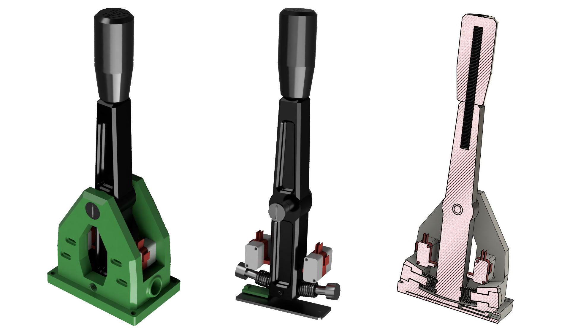
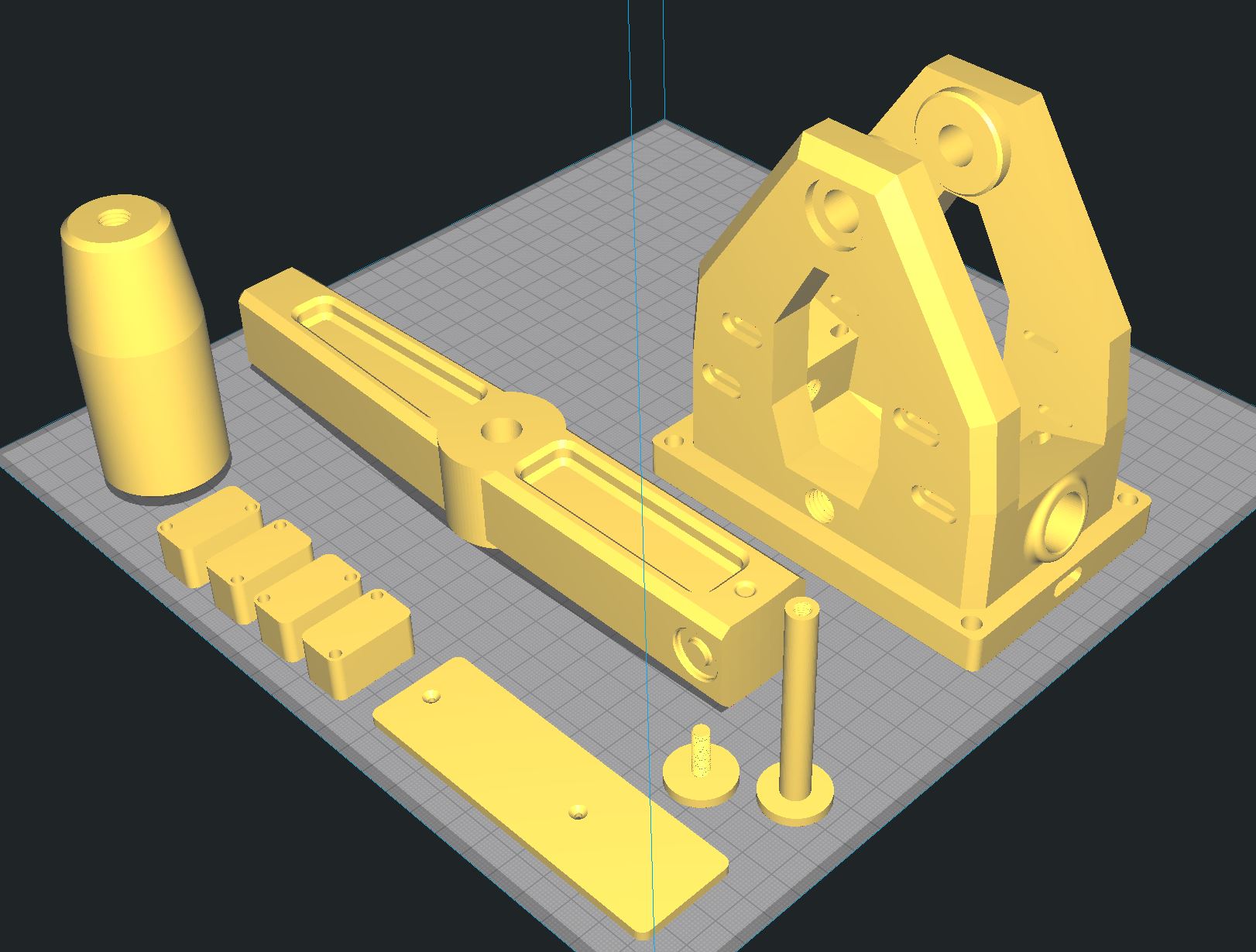
There are 6 components (2 of which are optional) that are required to be 3D printed. Their print orientation and required part strength does vary, but is relatively obvious. I have included an image of the ideal print orientation.
In total, print time will be about 1.5 days, and require around 500 grams of filament. I chose PLA and have had no issues with long term use.
Here is a breakdown of each part:
Main Shifter Body is printed standing upright, and with relatively high wall count and infill percentage, as the top section is under quite a bit of force when you smash through gears, particularly while in an aggressive race. I suggest 3 walls and around 50% infill. (Support material is recommended for this part)
Shifter Shaft is printed laying on its side, again relatively high wall count and infill percentage, much the same as the main body.
Bottom Cover is simply to retain and protect the arduino, does not need to be printed with any level of high strength, 2 walls, 10% infill.
Switch Spacers (4x) are printed on their sides with the holes facing up. These are not under very large forces, but may have some pressure applied when shifting, I went with 2 walls, 30% infill. Note that four of these are required, you may choose to print 2 rotated 180 degrees so that the side touching the bed is mirrored if you are pedantic like me.
Shift Knob (Optional) I have NOT tested this as I opted to use a real shift knob, but the model is there if you really need it. I would suggest printing it upside down.
Pivot Pin & Pivot Cap (Optional) These are only required if you opt for the metal pivot tube as I used, not require if you use a standard M12 bolt to retain the shifter shaft to the main body.
NOTE: You may need to use a 12mm drill bit to lightly ream out the holes of the shifter main body and shifter shaft IF you cannot get your pivot tube/pivot bolt into place cleanly, or if your shifter does not rotate smoothly. However, if you do this, do so carefully, or you will cause damage and need to re-print.
NOTE 2: You may need to clean up the M10 and M12 threads with a thread tap before assembly.
*Ideal print orientation
Part 2: Arduino Code
I won't detail the finer process on how to program an Arduino, but I have included my code for you with the files to download, plus the Joystick Library by Matthew Heironimus.
If you haven't programmed an Arduino before, there are PLENTY of tutorials and guides to get you started.
Some arduino code reminders:
Ensure you have your board type set to Arduino/Genuino Micro
Note that I have specified inputs 5 and 8 for the two shift switches, you can change them in the INO file if you prefer to use different I/O ports (it doesn't matter which input pin is used for up/down switches)
You need to add the Joystick library to your Arduino IDE.
Once the sketch is successfully uploaded to your arduino, you should now see the Arduino appear as a Joystick in your Game Controllers window (you can access this by typing "joy.cpl" in the windows start menu), and can test the two switch inputs by bridging the I/O port to ground with a length of wire.
Part 3: Wiring Arduino
Measure out 4x generous lengths of wire, 2 for each of the switches. Wire needs to be long enough to travel from underneath, up through the channels in the main shifter body, to the top where the limit switches will mount. Remember you will need two wires per switch, give yourself some extra length which you can trim down later.
Strip the ends of your wires and tin them lightly with solder.
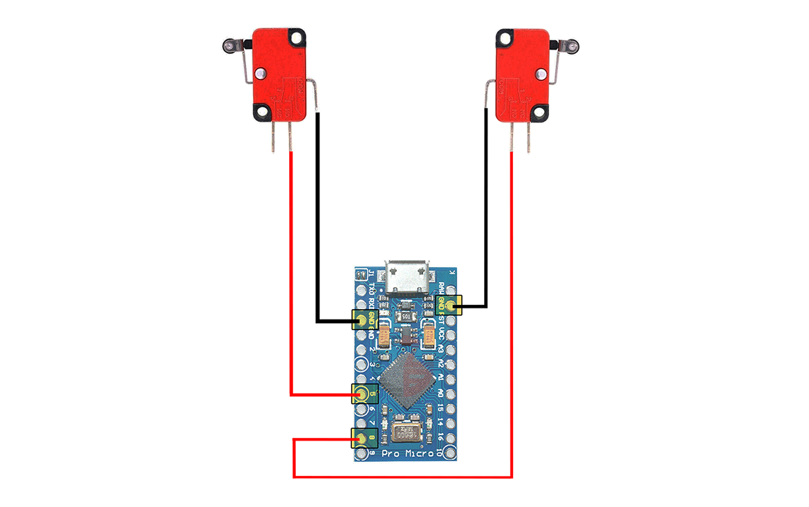
Solder the four wires to your arduino, one wire for each switch will go to the ground pins on the arduino, one wire for each switch will go to the I/O pins. Note by default the code specifies those as pins 5 and 8. If you chose to change those I/O pins to something else, ensure your soldered wires match your updated code.
Once soldered, route the wires up through the main shifter body and set the arduino in its final position, you may want to install the bottom cover now just to hold the arduino in place while we continue with assembly.
If, like me, you went for crimped lugs, then you can now trim the wires down to the right length then crimp your wire ends with your lugs to match the pins on the limit switches.
However if you prefer to solder the wires direct to the switches, we will do this later so move onto the next step (assembly).
*Wiring diagram
Part 4: Assembly
The physical assembly process is not overly difficult or complex, but some components can be a little "fiddly" to get everything to line up or fit in place.
Start by inserting the shifter shaft into the main body and align the pivot holes up.
Insert either the pivot tube or pivot bolt (with a washer) to act as the fulcrum of the shifter. If you opted for the pivot tube solution, it should sit flush with the inner edge of the main body on both ends, allowing room for the caps to sit flush with the outside of the main body
Note, you may wish to lightly lubricate the pivot parts for smoother operation.
Secure the pivot tube with the pivot pin & cap, these can be simply tightened by hand. Or secure the pivot bolt with the M12 nut and a washer.
Install the shifter travel stopper bolts into either side of the lower part of the main body, these will limit how far the shifter can swing back and forth, and can be adjusted to define that limit.
Now is also the time to install the shifter springs. This sit over the travel stopper bolts, and add "tension" to the shifter, and help keep it centered. These are perhaps the hardest part of the install as they can be tough to get in place.
Install the limit switches to either side of the shift lever. Each limit switch has one of the switch spacers set either side of it, with the long M3 bolts securing them in place. Don't forget a washer for each bolt.
Take care to route the wiring to the outside of the switches so that it is clear and not snagged in any way.
Secure the limit switch long M3 bolts with their nylock nuts and washers, I chose nylock to avoid the nuts coming loose.
Note, there is plenty of adjust-ability in the switches so you can again choose the travel of your shift lever before the switches engage.
Install the wiring onto the switches, either by soldering them onto the switch pins, or sliding on your crimped lugs.
Thread the M10 stud into the top of the shifter shaft and then thread on your shift knob of choice.
If you opted to include ball plungers, thread them into the sides of the shifter main body and leave the relatively loose for now, you can then tension them up later once you start to use the shifter and "wear it in".
Now connect the micro usb cable to your Ardunio, and if you haven't already done so, secure the bottom cover with two small screws.
Part 5: Install and Test!
The shifter main body has 4x perimeter mounting holes that accept M6 bolts, their pattern is 116mm apart on the length, and 74mm apart on the width, centre to centre.
These can be used to affix to your racing sim rig, you will need to find some form of bracket / plate to suit your particular rig.
Once your new shifter is firmly affixed to your rig, connect the USB cable to your PC, open Windows Game Controllers by typing "joy.cpl" in the windows start menu, and verify your shifter is detected as a Joystick.
Now, launch your sim game of choice, map your shift up/down keys and enjoy your racing!
Your awesome new shifter is now finished, congratulations!